Expert Systems 9501 Tinker Court Burke , VA 22015
|
|
Expert Systems 9501 Tinker Court Burke , VA 22015
|
Isolation equipment is readily available that will protect wire-line communications facilities entering PCS locations within high-voltage corridors from a GPR as high as 50 kV rms and 90 kV surge. Properly installed, this isolation equipment will offer many years of maintenance-free, reliable protection from the effects of GPR. Those PCS locations within high-voltage corridors that have overhead ground conductors (OGC) with no neutral will experience theoretical GPR levels under 45 kV peak, provided that the PCS grounding system resistance is less than 5 ohms. If a neutral is also present in the overhead, the theoretical GPR levels will be less than 20 kV peak. This represents the vast majority of the type of high-voltage corridors in use today, and these magnitudes can easily be isolated with equipment available on the market. The PCS locations within high-voltage corridors that have no OGC and no neutral will experience much higher theoretical GPR levels, even with a 5-ohm PCS grounding system at the tower base. This is because all of the fault energy will pass down through the single tower into the ground. Worst case theoretical GPR levels under these conditions could reach a maximum of 85 kV. Note: Actual real-life GPR levels much over 30 kV peak asymmetrical may not occur, because earth ionization increases the earth conductivity if the current density becomes high enough. Obtaining less than 5 ohms for a PCS grounding system in poor resistivity soils may be very difficult at a cell site with a small grounding system. However, significant grounding improvement to these small grounding systems can be obtained without expensive or elaborate grounding systems, as one of the authors has shown.
II. GROUND POTENTIAL RISE (GPR) Electrical damage from ground potential rise (GPR) throughout the wireless industry has an estimated cost in the many millions of dollars each year, but few engineers in the industry are even aware of the phenomenon. Most times, the first sign that something is wrong comes right after a thunderstorm or after a fault on the power line. Suddenly, the wire-line service coming into your cell site has failed, and the delicate circuitry of your communications equipment is damaged. This is often misdiagnosed as an unavoidable maintenance problem, and much money is spent on repairing equipment and replacing protective fuses and gas tubes C to say nothing of potential lost revenue. In the worst case, the safety of personnel working at the site may be seriously compromised.
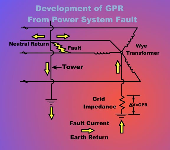
III. SOLVING THE MYSTERY In reality, this type of damage very well could be due to a phenomenon called ground potential rise (GPR). When a ground fault occurs at a power substation, some of the fault current will return to its source, namely the substation transformer, via the earth, through the substation's ground grid (Figure 1). This ground grid has its own characteristic impedance. Following Ohm's law, a current passing through an impedance will result in a voltage. This increase in the potential of the grounding system, referenced to remote earth, is called ground potential rise (GPR).
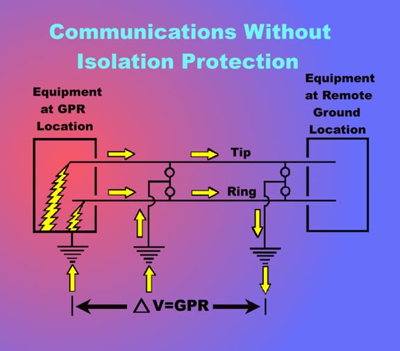
As Figure 2 shows, if your telecommunications lines coming into a cell site are copper, and if these lines are not properly isolated, they provide a path for the voltage impulse coming up from the grounding system, whether from lightning or a power fault as discussed earlier. Normally, communications engineers look upward for threats in the electrical environment; but this one comes from below, from the very grounding system that is part of the electrical protection scheme. This threat is real and can compromise personnel safety and damage equipment.
IV. GET TO KNOW THE STANDARDS Follow existing national codes and IEEE standard installation procedures while using HVP devices. The most important standards include: O ANSI/IEEE Standard 487-1992 - Guide for the protection of wire-line communication facilities serving electric power stations.O ANSI/IEEE Standard 367-1996 - Recommended practice for determining the electric power station ground potential and induced voltage from a power fault.O ANSI/IEEE Standard 80-1997 - Guide for safety in AC substation grounding.O NFPA 70-1999 - National Electrical Code.Communications protection engineers should not turn a blind eye to GPR damage because they believe special HVP devices are more expensive than gas tubes. Consider ongoing costs for continually replacing damaged equipment year after year. Also consider that the costs of labor for repairs and the lost revenue from downed communications lines can easily surpass the cost of GPR protection. And don't forget personnel safety and liability issues: employees working in, on, or around equipment connected to a remote ground potential are at a safety risk if standards and codes are not followed. Properly protected GPR locations, designed and maintained by trained employees, will reduce overall costs, improve productivity, and increase circuit reliability over any time period.
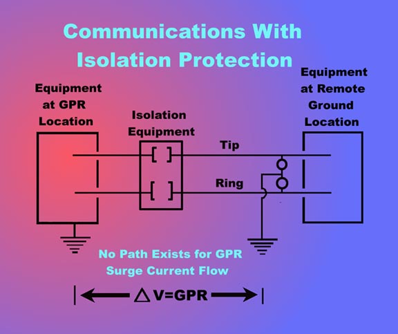
V. MODERN GROUNDING TECHNOLOGIES As can be seen in Figure 2 above, the GPR voltage can be reduced by bringing the resistance at the communications location (cell site) to a low level with respect to the remote ground location, effectively shorting out the GPR. The trend among wireless service providers is to specify a resistance to remote earth of 5 ohms or less. A low ground resistance produces the following benefits: O Reduces touch and step potentials, which are dangerous to personnel O Reduces voltages across insulators that can cause current flashover across the insulators O Reduces the likelihood of side flashing, or arcing through air, between exposed and grounded structures and components O Diverts lightning current around concrete tower foundations, which can be exploded by the current O Facilitates the discharge to ground of currents intercepted by protectors and arrestors O Keeps GPR within the specifications of HVP isolators. Modern lightning research has led to improved understanding of the lightning threat. It has shown the wave shape and magnitude of lightning strokes. This has shown the importance of low-impedance as well as low-resistance grounds, since the destructive voltages developed by fast transients such as lightning depend more on the inductive-reactance component of the impedance than on the resistance. However, it is usually easier to calculate, predict, and measure the resistance of an electrode than the inductive and capacitive reactances. Fortunately, if we design and install an electrode for a low resistance such as 5 ohms, it also tends to have low reactances.
VI. THINK LATERAL When a really low resistance is required, the best advice for the grounding designer is to "think lateral," especially when the soil is highly resistive or too thin to allow driving rods. A flat electrode of significant lateral extent, at a shallow depth of only 30 in., may be the best or only option. It resembles a buried plate, which provides a highly capacitive electrode. The resistance of an electrode is inversely proportional to the capacitance. In fact, the formula for resistance of any earth electrode is based on the capacitance between the buried electrode and its hypothetical image above the earth. Conductive cement such as EarthLink from Grounding Systems provides an easy, economical way to design and install extensive electrodes. The cement is employed as a backfill material around commonly used metallic electrodes such as driven rods and buried wires (counterpoise) and rings, increasing their cross-sectional area by a factor of 100 or 200 (for a 4/0 wire) or even more. In many adverse grounding situations, the conductive electrode may be the only economic and practical method of obtaining 5 ohms. Cement can be used to augment almost any kind of electrode, and the results are easy to calculate and predict and are permanent. Cement is well known to contractors to protect buried metal from corrosion. Not just any kind will do for grounding, however. Conductive cements have over 200 times lower resistivity than ordinary cement C low enough that standard formulas can be used for calculating the resistance of electrodes made with them, just as if the electrodes were made of metal.
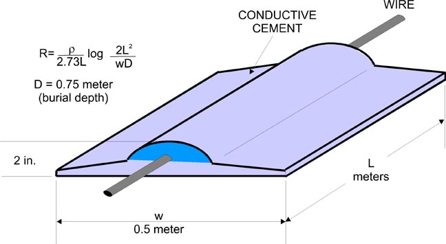
Figure 4. Conductive cement effectively enlarges the wire, Figure 4 shows a horizontal-strip configuration, or groundbed, and the formula for calculating its resistance. The most common installation procedure follows: 1. Dig a trench, 30 in. deep, 20 in. wide, and as long as required to obtain the desired resistance. (The length is a design calculation, discussed later.) Center a 4/0 stranded wire in the bottom of the trench. 2. Pour in the cement as a dry powder (it will later absorb moisture and harden) by dragging an open bag of it down the trench. Use one 50-lb bag every 10 ft. Heap the cement up as shown. 3.`Lift the wire slightly so it is completely covered by the cement for corrosion protection. Tamp the cement with feet or a shovel toward the tapered edges. 4. Carefully shovel in a 4-in. layer of soil and tamp it down. 5. Push in the rest of the removed soil using construction equipment.
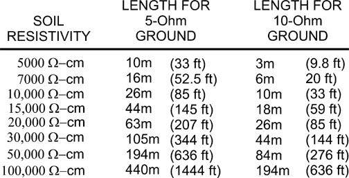
VII. DESIGNING A HORIZONTAL ELECTRODE The design procedure is as follows: 1. Decide upon the desired resistance of the electrode. 2. Measure the soil resistivity with an earth tester. 3. Determine the required length from the table, based on the desired resistance (5 or 10 ohms) and the soil resistivity.
Table 1. Table of lengths for 5- and 10-ohm grounds. VIII. GROUND RING A typical pad-mounted wireless site has a buried ground ring around the pad, about 2 ft out from the pad, and another ring around the antenna. The formula given in Figure 4 applies; however, the resistance thus obtained must be multiplied by 1.12 to account for the reduced grounding efficiency of a square ring compared to a straight strip. For example, if the two rings require 145 running feet (44 m) just to surround the pad and antenna, the table shows this would give about 5 ohms in 15,000 ohm-cm soil (about 1.5 times the average U.S. soil resistivity). Multiplying by 1.12, the resistance would be about 5.6 ohms. A still lower resistance could be achieved by extending radials from the four outer corners of the configuration.
IX. GIRD THE GRID Meanwhile, back at the substation, the source of the GPR from power faults, the GPR can be reduced by lowering the resistance of the grounding grid. If conductive cement is used to surround grid wires on a 10-by-10-ft spacing, the grid area can be reduced by 10 or 20 percent, with a concomitant money saving and reduction in the extent of the critical 300-V GPR contour. Use IEEE Std. 80-1997 data or EPRI Substation Grounding Workstation software and assume strip conductors of 2-in.-by-18-in. cross section. For further information, refer to manufacturers' application notes. Existing ground grids also can be improved by extending the grid area by 10 or 15 percent and using conductive cement. In one application in high-resistivity soil, grid resistance was reduced from 10 ohms to 2 ohms. In another, resistance was reduced from 0.96 to 0.2 ohm. Consolidated Edison and Boston Edison have used conductive cement to ground transmission towers and substations.
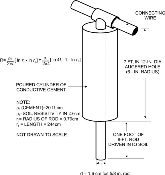
X. EMBEDDED GROUND ROD About 50% of the resistance between a ground rod and remote earth is in a shell within the first 6 in. from the rod. If this shell is shorted out by encasing the rod in 6 in. of conductive cement, as shown in Figure 5, the resistance is halved. This is a good example of how the resistance of any electrode can be decreased without making the electrode longer. This is important wherever bedrock limits the length of ground rods or when property lines limit the length of a horizontal electrode.
50 percent of the earth resistance is within 6 inches of the rod. REFERENCES Positron Industries, Inc., Teleline Isolator Product Guide, Montreal, Quebec, Canada, 1999. Grounding Systems Co., Application Note TD-1, Ground Grid Improvements and Extensions, Chagrin Falls, OH, 1999. C. L. Hallmark, Horizontal Strip Electrodes for Lowering Impedance to Ground, INTELEC 97 Proceedings, Sec. 17-2, pages 368-375. Gilbert Sharick, Grounding and Bonding, Vol. 13 of abc
TeleTraining Basic Series, abc TeleTraining, Geneva, IL, 1999. |
||||||||
New! Lightning Protection Checklist for Risk Management New ! Lightning Protection Guide for protecting equipment and personnel New ! Lightning Storm Dot Com view the current lightning map of the United States New ! Lightning and GPR Related Links New ! Lightning Related Articles New ! Lightning Related Reference Books New ! Wire-Line Communications Isolation or Fiber Optic Facility Extensions ? Solving High Voltage Problems In Wireless/Utility Collocations Eliminating Lightning Damage at PCS Cell Sites Isolation of Wire-line Communications in an Unregulated Power Market PCS Locations in High-Voltage Corridors Be alert to the Danger of GPR On the Road With Ernie Great Balls of Fire! Destructive Surges Wireline Isolation Theory and Application When to Protect Cell Sites from GPR Links to US Energy Utilities Communications Related Links Return to GPR Expert Home
|